


Martinb
-
Posts
101 -
Joined
-
Last visited
Content Type
Profiles
Forums
Gallery
Downloads
Articles
Posts posted by Martinb
-
-
Click PORTAL up top and donate is over on the right hand side (see pic)

-
 1
1
-
-
8 hours ago, EdwardFarmer said:
You can use any hopper if you use infrared sensors to register the coin output
Thanks yes did consider that type of idea but luckily I got them working so all good
-
13 minutes ago, slotsmagic said:
Does yours have a VEGA note acceptor and recycler unit like mine had? I have a spare NV9 USB with new notes and a stacker that I was tempted to try but it's really not necessary for me. I do feel the VEGA with recycler might cause more issues than it's worth
")
Yes same has a vega but I have an NV9 which I’m tempted to play with
-
8 minutes ago, slotsmagic said:
That's not a bad idea at all. I probably ought to stick my Barcrest PSU back in. I ran everything off the PC PSU in the Vegas Strip due to the 'common ground' issues I read about, and the fact that the hopper runs great on 12V but am not sure that overloading my little small form factor PC PSU with a load of additional stuff is a good idea
I'm sure all the pinouts are clearly labelled on the PSU so hopefully I'll be able to work something out. Probably should have kept the original loom for the plug that goes to the PSU, but then since I'm not using that many pins I'm sure I can bodge something suitable0
Yes and I forgot the coin mech is also powered from the original Barcrest PSU.
The existing loom made my ipac/pac drive wiring really easy and the tri colour buttons are great - so much so I have ordered the ID2 Pac drive so I can have all RGB on each button active for theme colour matching (21 outputs). I quite like matching the button colour and positions to the layout but its all time consuming fun lol
I am wondering now about the note acceptor
-
2 minutes ago, slotsmagic said:
For the parallel hopper motor power, are you using the 24V of the NUC PSU, or an output on the original Barcrest PSU? I kept the original PSU and would happily use it
I used the original Barcrest PSU 24v. I also use this PSU for the other hopper (although I opted for 12v to slow it down) and the cabinet fans oh and the coin tray light. It also powers my small amplifier (12v). The 5v was mainly for the relay and also the compact hopper opto circuit.
-
 1
1
-
-
2 minutes ago, slotsmagic said:
It's bonkers

Just wondering - with your parallel £1 hopper, what are you using to power it? My relays arrived today (going to make a little board to drive it as shown in @davep180's thread), but just wondering if you are driving it from a 12V rail off your PCs PSU, or a separate PC PSU, or perhaps even a normal fruit machine PSU with 24V?
Annoyingly I ended up with 3 PSU's:
1. 5V PSU
2. The original Barcrest PSU (no 5v annoyingly)
3. The 24v PSU for the Intel NUC PC
I just connected the ground on them all to ensure all the signalling to the ipac worked correctly.
The Hopper relays I used are slightly different but I had 5v connected to the relay and then the pac drive output as the 5v trigger on the one side and I switched ground for the £1 universal hopper but the compact hopper needed a +12v switch as the ground was also used for the opto circuit. That make sense?
-
25 minutes ago, slotsmagic said:
Hopefully this helps a little bit.
Got it spot on thank you so much!! Just got it working on a Scorp 4 I am messing with but yeah I get the jist.
How awesome is all this stuff !
-
15 minutes ago, slotsmagic said:
You've lost me there, do you mean that you have a game that isn't accepting 10p or 20p inputs? Before I got in to cabinets myself and I think most others only included a £1 input - typically the lamp for the coin entry, if you right click on it and look at the properties, you'll see that it's got a coin type set to it.
To enable the other coins to work, you need to make other coin entries - they could be buttons or lamps. You then need to set the keyboard shortcuts to these to match your iPAC. On my current layouts I typically use (where the first number is the keyboard shortcut) :
0 = £1
9 = 50p
8 = 20p
7 = 10p
6 = 5p
Yeah sorry to be clearer I wanted to have a 10p coin register as 10p as all I can seem to do atm is £1 (or 10p on older games)
I can do exactly as you said looking at the bezel in edit mode / properties and add the coin mech no problem for a pound (for example) but how would I add 10p and 20p etc to that same machine?
I have done all the ipac parts and they all work for all coins
So how do I make other entries please, dummies guided lol (or link me to a post where its been asked I have had a search earlier and couldn't see anything but of course there is a lot there)
Thanks
-
Another possibly already asked question apologies - how do I set 10p and 20p as credits on the games please from the coin mech?
-
15 hours ago, davep180 said:
Not sure mate. Use Triac ->Hopper (1 or 2) Then put the Triac number from the diag in the box and add a multiplier, even if it’s just 1.
You are a hero that worked in line up so I’ll persevere with the others thanks a lot Dave
-
2
-
-
1 minute ago, Martinb said:
Thanks Dave I am almost certain thats what I tried on line up but I will have another go in the morning at play time. I was driving me nuts earlier!
Having said that I did not put a label could it be that? I presumed that was just a text reference (optional)
-
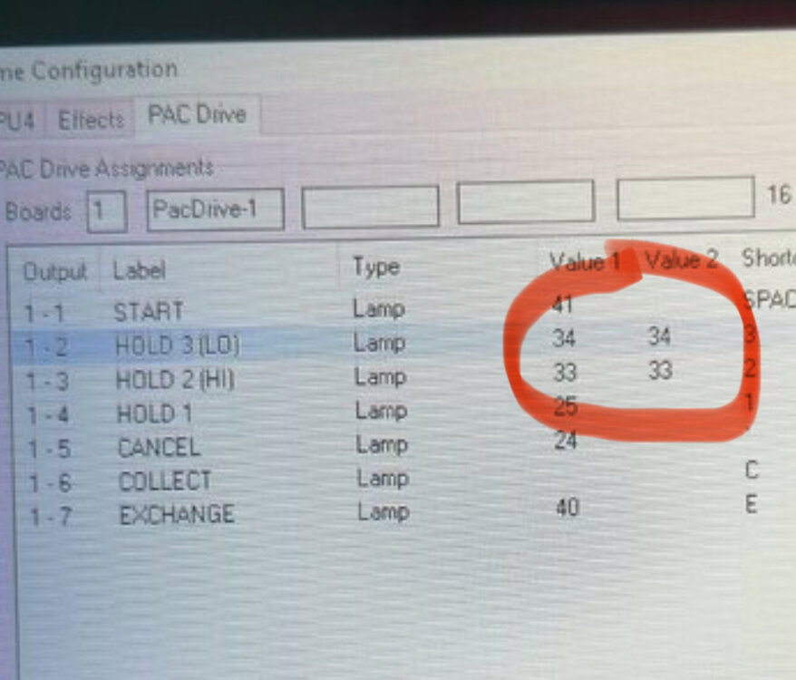
4 minutes ago, davep180 said:
Here’s my config screen for Line Up. My 10p hopper is hopper 2. Hopper 1 is £1’s. On the diag screen 10p is Triac 1 and the token is triac 2. Value 1 is the triac number and value 2 is the multiplier (you can do 20p as 2x10p or 50p as 5x10p)
Thanks Dave I am almost certain thats what I tried on line up but I will have another go in the morning at play time. I was driving me nuts earlier!
-
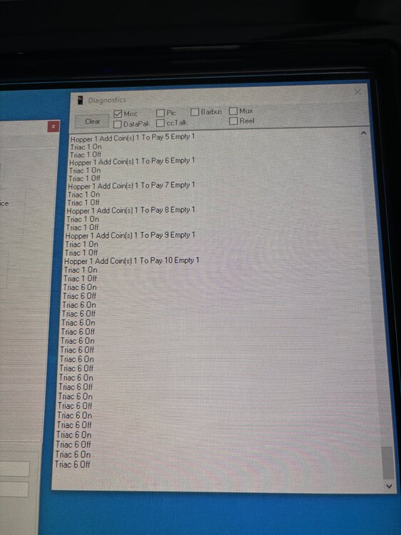
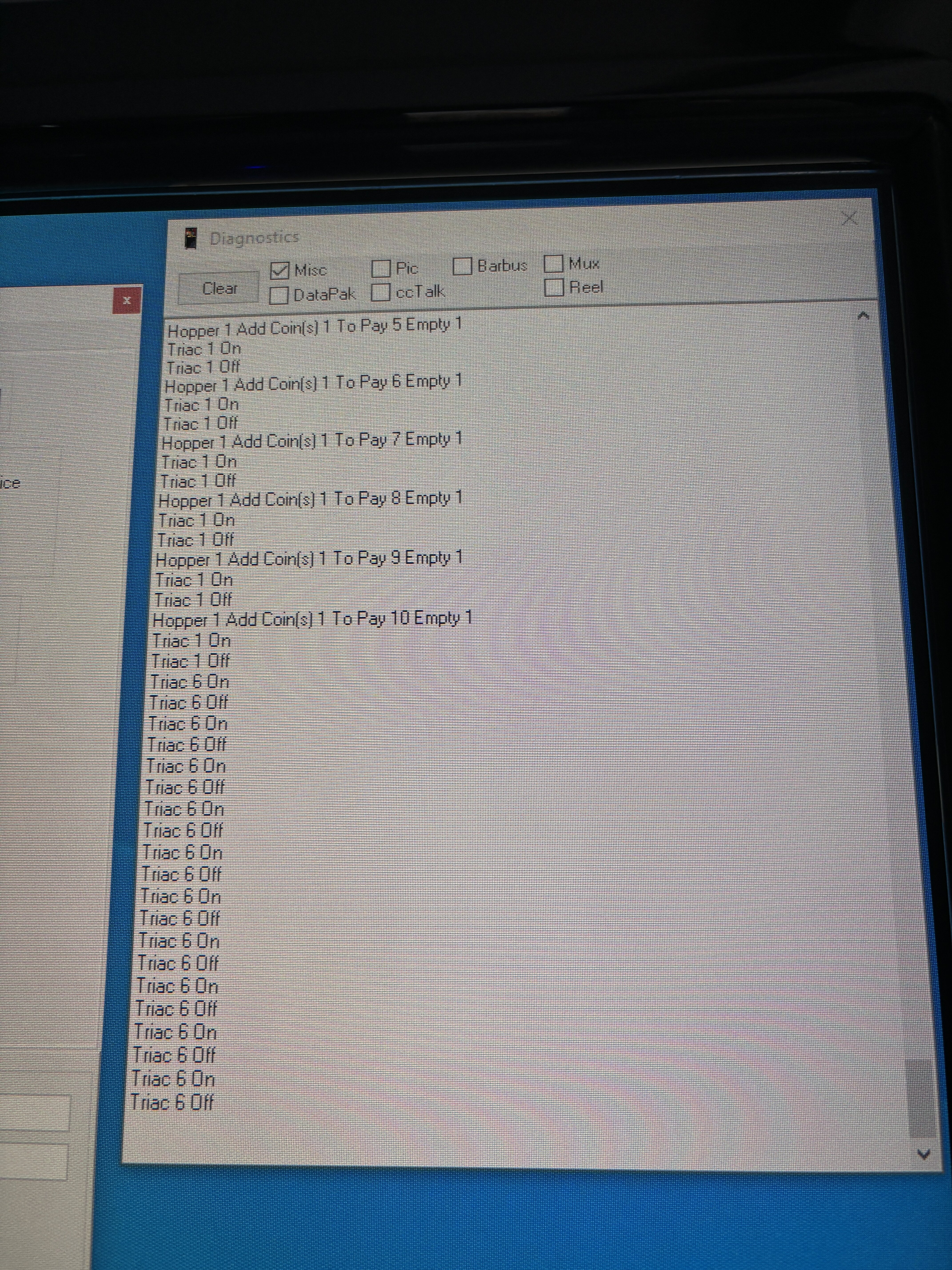
Quick question on the hoppers please (I have had a quick scan and could not find anything) I have them working perfectly on machines which use hoppers eg Scorp 4, 5 and MPU5 etc but on the older stuff like System 5 and MPU3 no matter what I do I cant make the triac-hopper function work, or is it me? I am testing on Line Up and also Fairground Club (JPM) but I also tried MPU4 rocky horror.
I can make the triacs pulse the hoppers (like a solenoid) but not triac-hopper.
I noticed on diagnostics this on each of those I was trying too might be a clue? Add coins?
I may have it all wrong in my head so hoping someone can educate me pleaseeeeeee
-
Front end menu next for me, here is a very quick video of it in action so far

-
2
-
 2
2
-
-
2 minutes ago, dondplayer said:
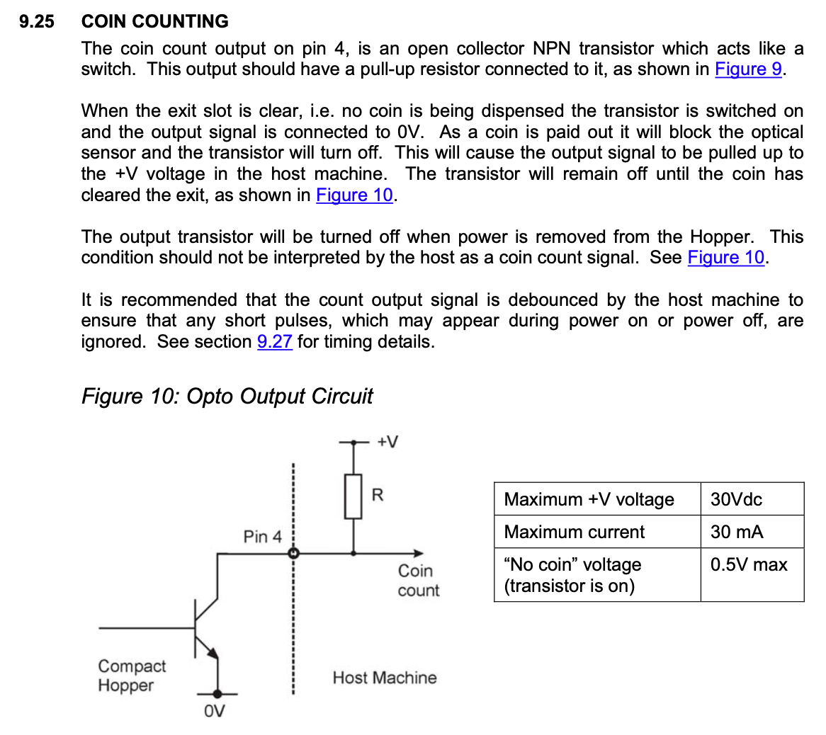
I wonder whether you need either resistor, this depends on what is present on the hopper output pin 4 when it's not pulsing +5v and how the IPAC reacts as if disconnected.
So if hopper output pin 4 is ground when not pulsing +5v that would give ground at the base with ground at the emitter so the collector to emitter would be no flow.
Mind you for the sake of two resistors it's all good.
The first resistor is defo required as per the specification, the second not so sure, but yeah it works
-
1
-
-
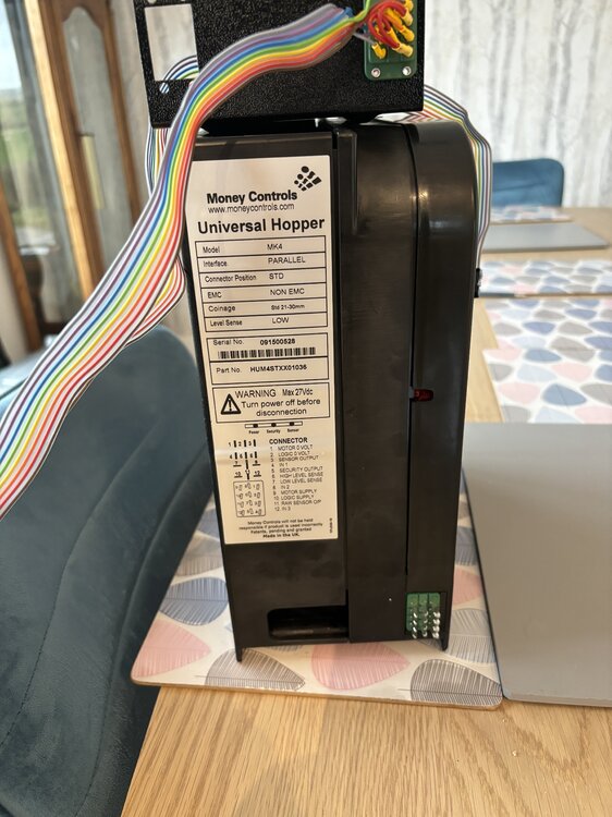
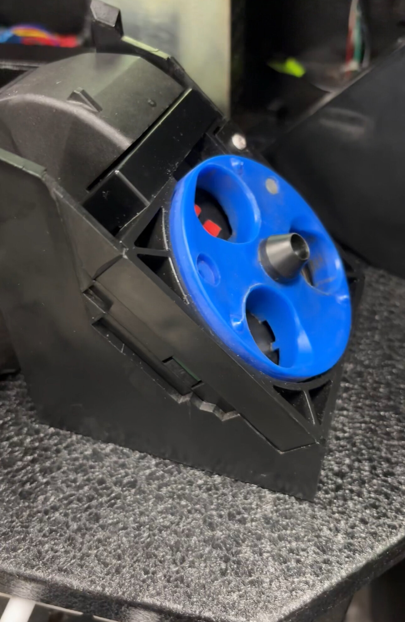
OK so I now have both hoppers working. The wiring for the Universal hopper (£1) is per Dave's post as I linked above and it worked a dream.
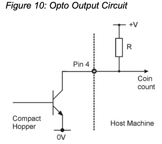
The compact hopper (10p) parallel is a tad more complicated simply because its opto outputs +v and the ipac wants a 0V (GRND) input. I reversed this with an NPN transistor (I used a TIP 121) and ideally need to make up a small board to do the magic as it requires 2 pull up resistors as well - that all sounds very complicated but honestly with some wago clips, 2 resistors and a transistor (as it is at the moment) it isn't and in my case with this cabinet its important the original hopper setup worked as modification to fit other hoppers would have been even more difficult/messy that a few extra components.
So there are 4 wires off the hopper
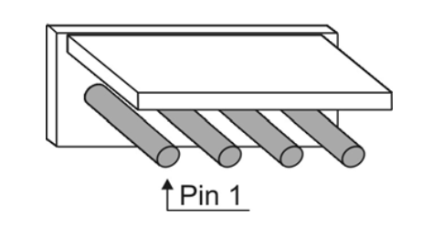
Pin 1 Is the motor switching +12 or 24v (depends on the model, most are 24v but I am using 12v to slow it down) - this goes to the relay controlled by the PAC Drive
Pin 2 is GROUND (just remember to link the grounds up if you use different PSU's like I ended up doing)
Pin 3 Is +5v its the power for the Opto circuit
Pin 4 Is the coin counting output (opto) and this is where the pull up resistors and NPN transistor are needed and then connects to the Ipac
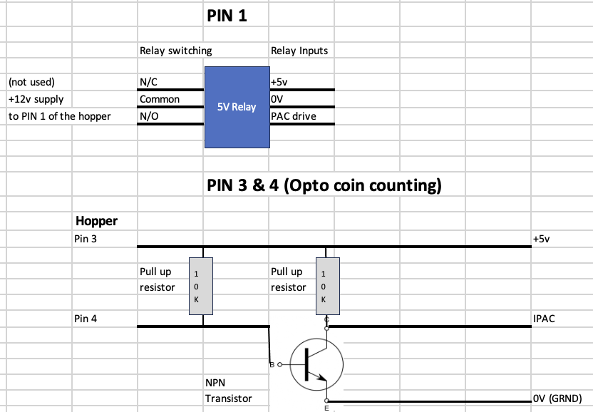
I am not convinced the second pull up resistor is needed and may try without it but it works like this at the moment beautifully.
Ps - if like me you get a parallel hopper with the later added security board (causing it to inch when you apply motor power) then its simply a case of removing the small white cable from the motor and it will work normally.
-
45 minutes ago, Ginge said:
I know the feeling
 .
.
So do I

-
1
-
-
That layout has its own dedicated hi lo buttons so that’s likely the problem as you said - I’ll have a tinker on mine too as that’s an interesting one
you seem to have duplicated the lamp number tho?
-
12 minutes ago, slotsmagic said:
Brilliant!! That's exactly what I'm hoping to do with mine. I'm assuming you had to use a relay with the parallel hopper? Would you be willing to share a schematic or just picture of the parts used?
Absolutely I will, just let me get the 10p compact hopper one working that’s been the challenge - Dave / @WibbleWobbledid the hard work on the universal £1 one as I linked above so you could get yours pre wired ready
Have you got a parallel hopper to use?
-
23 minutes ago, davep180 said:
Those mk4 hoppers are rapid too! Nice one @Martinb. I must say that it was @WibbleWobble(hi mate, hope all is well) who first got that hopper going for me, I just did a write up for it. Glad it’s helped someone out though.
Yep thanks Dave I did your wiring all ready prior to the hopper arriving today and boom it worked from the off thank you.
-
1
-
-
Yaaay the pound one worked a dream I'm buzzin lol
-
3
-
1
-
-
Quick update - I have been having fun with a money controls parallel compact hopper notably regarding the opto output but I have finally cracked it and the ipac now sees coins as they fly out. Basically it (by default) outputs +v and the ipac wants ground so a NPN transistor later and a couple of pull up resistors and a lot of head scratching but I have a working hopper.
I also got tricked by apparently a later mod done with a security board that every time I tried to power the hopper it just inched and stopped - I found the circuit and was able to disable it. This was apparently to stop the direct feed to payout from attacking the machines supposedly.
Onto the parallel £1 one now, already proven uneversal hopper so fingers crossed @davep180Dave your schematic works in one (no pressure lol).
The hope very much is the interplays original setup for coins in and out is still part of the build, hence using the same hoppers (just parallel).


-
1
-
1
-
-
7 hours ago, slotsmagic said:
I would assume (but could be massively wrong!) that if you had your buttons spread across both banks (that's a lot of buttons!) you'd want to run separate grounds to them - so a daisy chain of wires from the buttons on one bank to that bank's ground, and then the buttons connected to the inputs on the other bank would have their own ground wires.
Understand the thinking but not necessary at all on these inputs, the grnd (or common in this case) to each pushbutton can be daisy chained no problem to a 32 inputs if that many was required.
I am like you tho, my second grnd is used for payout but they are basically the same just the ipac provides 2 terminals for ease.
-
1
-
-
I do use a hub but only for low power devices like keyboard, mouse and touchscreen but if you have enough for what you need than no need for the hub no.


Finally I am doing a cabinet! (Interplay donor)
in Cabinet Building
Posted
Not commercially no, but you can do one yourself or buy one already done by someone else, but, they do require almost continual tweaking as you load different games and need to map buttons, payouts, lamps, screen sizing etc. It’s well worth it tho and you can use front end menus etc for launching games ….. it’s how far you go I suppose
I’m hoping to finish mine off with a front end once I get some time to tinker …. winter tends to be tinker time hahaha