


No1Stoney
-
Posts
427 -
Joined
-
Last visited
-
Days Won
17
Content Type
Profiles
Forums
Gallery
Downloads
Articles
Everything posted by No1Stoney
-
Remember if you're using a pc power supply on its own, you need to bridge 2 pins together (i can't remember which, just Google it) to make it come on when the power is applied.
-
the only wire from the hopper to the ipac should be the coin sense wire
-
Yes you shouldn't have them in the ipac. It should be in the gnd of the 12v source
-
The 3x 12v wires I join into 1 single wire and I've done the same with the 0v
-
Your wiring seems correct. 3x 12v feeds and 3x 0v. That should work. Where are your gnd wires currently connected to? They should be connected to the 0v of the 12v feed. Mine connects to the pc 12 and pc 0v
-
Thats correct its currently on mode 1 (no jumper present) on those pins above the sticker. Have you tried going into mfme and clicking test hopper button under pacdrive settings. If your hopper is powered this should start the motor of the hopper. That will tell you if its wired up OK or its a setting that's not right.
-
Check your hopper doesn't have a jumper pin attached . If it does remove it so that it is on (I think) mode 1? Not at home at the minute to check mine but there is a jumper pin on these hoppers which make it work in different ways. Remove it if there is one. Everything else seems setup correctly. If its not firing up at all its something with either the hopper, pacdrive or mfme settings. We can rule out pacdrive for now as that only triggers the hopper to stop. These hoppers don't have an led light.
-
No problem. Has it helped with the hopper and lights ?
-
On the config screen you need to click the 'config' button to map your settings to the machines lamp numbers. When you click config you will see it will populate the numbers in the value box. Think this also sets up the hoppers.
-
That's strange. Like its not detecting your ipac. Is it definitely powered? Change usb port ?
-
Yea that's right. You can choose exactly what key each coin will 'press'. Just set the same shortcuts in MFME.
-
Hi. As long as you wire the mech up as shown it won't need any configuration as long as you don't fiddle with any dip switches or anything. For the wires that go into the IPAC it doesn't matter which inputs you choose to wire into. As long as only the one labeled GND goes into one of the 2 ground pins on the IPAC. as far as WinIPAC goes, you can configure it to act as any key you want as the coin mech will now act as a keyboard with a different key per coin. You then need to add coin inputs with the same shortcut as you've chosen on WinIPAC onto each MFME layout you add to your cab. Hope this helps
-
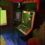
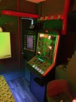
Building an idea WibbleWobble's MFME Cabinet build
No1Stoney replied to WibbleWobble's topic in Cabinet Building
Looks impressive. You've gone for a similar layout to mine. Although mine is a lot more rough round the edges . I too had an issue with the monitor getting in the way and had to cut a chunk out of the monitor mount. Looking forward to seeing the progress. -
One going cheap here: https://www.ebay.co.uk/itm/254685250359 I have this one and it works just fine on 12v. Slower spin than on 24v but its still pretty quick
-
I wouldn't get that one. It will be complex to wire up if possible at all. There are much easier alternatives. Universal hopper or azkoyen u2 (that's what I use and its a piece of cake to wire up) parallel versions
-
The bottom pins are output/0v pins so need to goto the 0v on your 12v power supply. All those pins can be connected to the same 0v source. On my build I use a connector to join those wires together into one single wire that then goes into a 0v source. The wires that goto the ipac (red on my diagram) can be any of the connectors on the ipac it doesn't matter which. As long as the ground one is connected into one of the 2 ground connectors on the ipac. If your using a different 12v source just make sure that the 1 pin from the mech goes into your 12v source instead of pc molex. Study the pins exactly though as you risk blowing it up if you don't look at it carefully. Specifically the 12v pin is amongst those 0v pins
-
Just read my previous posts, I put a diagram up which tells you how to wire it up
-
Looks smart that. I like the layout of the buttons for all different games. Especially the arrow buttons on the main panel. Good Job!
-
Yes of course you could. And you will need to make something to hold the mech to your cabinet too. I was lucky and found someone selling the metal work from a real fruit machine so I bought that. Good luck with the build. Keep us all updated, looking forward to seeing how it comes together
-
https://www.ebay.co.uk/itm/COIN-MECHANISM-ENTRY-PLATES-AND-HOLDERS-MARS-COIN-CONTROLS-NRI-CASHFLOW-AND-AWP/223547118473?hash=item340c725389:g:o2kAAOSwJSJc~jX0 The one the seller has listed as a double entry, thats the one I use for that mech. You may also need to buy a coin mech holder or make something that the coin mech will sit in. See above posts for mech wiring diagram Also you will need this. It goes between the coin entry slot and the mech https://www.ebay.co.uk/itm/Mars-coin-mech-Y-chute/164130037714?hash=item2636e99fd2:g:PqUAAOSw5iNecjaG Just double check its defo the one for your mech
-
No, its a serial hopper. The pinout label says 'Data' and 'NC' etc . Look for one (if you choose this type of hopper) that has 'Control' and 'Coin' etc as that one is the parallel version you need.
-
They will go straight into those buttons without any modification. You will still need a 12v source for the coin mech and hoppers. Some hoppers require 24v
-
Here is the bulbs you can use: https://www.ebay.co.uk/itm/122265668678 Seller also does different colours and pack sizes
-
As wizard has said, its better to use 5v leds in the buttons. You can simply swap out the existing bulbs for led ones and use the buttons you have already purchased. I wouldn't bother with that power supply as you need to connect the 12v source to wiring inside your machine and you can do that from the power supply which will drive the pc.
-
Diagram

