


No1Stoney
-
Posts
427 -
Joined
-
Last visited
-
Days Won
17
Content Type
Profiles
Forums
Gallery
Downloads
Articles
Posts posted by No1Stoney
-
-
If you hold the test button it should keep the hopper running until you let go if I remember rightly. Progress at least!
-
28 minutes ago, Psycon said:
This is how I have mine setup. The only difference I can think of is yours runs the pc power from the same pc as the usb's. But surely if there is a 12v source it shouldn't matter? I'm thinking it's more they arnt getting a signal to motor start? The issue I have is I can't take a 12v sorce from the pc board running it

It might matter though as they are running on separate circuits you see. If you can try the other way then give it a go. If nothing else it will eliminate that being the problem . There should easily be a wire you can splice into from the pc that runs the usbs.
Its also the thing that both you two have in common. A separate psu.
-
I still am thinking this is to with 'common ground' issues. On my cab, the USBs are plugged into the PC. From that same PC, I've used the PSU from it and spliced into a 12v/0v wire to power my devices. This means that the USB and my devices share the same ground/0v. If you are using a separate PSU to the one that powers your PC, your USB ports are on SEPERATE ground/0v to the devices, if you see what I mean.. I'm thinking this is possibly your issue.
@Reg do you have any thoughts on this?
-
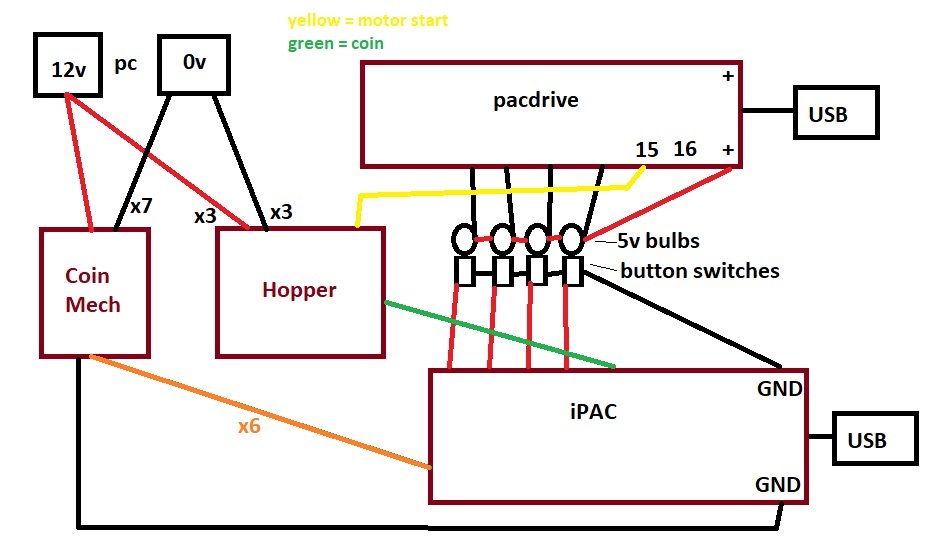
OK guys, I'm a little stumped as to why its not working. So for clarity, this is the way it should be wired as this is currently my setup.. Apologies, I remembered I upgraded to 5v bulbs when I modified my cab a few months ago. However that shouldn't make any difference. For 5v bulbs, make sure its wired like this. If it is, then your issues are not a result of how its all connected.
-
So This is my setup
PSU 12v ---> pacdrive lamps daisy chained (mine are 12v bulbs)
---> hoppers x 2 ------------------------------------> | <--- Pacdrive '+' port
---> Coin mech ------------------------------------> | <--- IPac 'GND' port
|
PSU 0v <-----------------------------------------------------------|Hope that makes sense. But as you can see all the devices return to the same 0v black wire on the PSU
-
So for example, 1 negative lead from the PC PSU splits off to all your device's negative wires. If you get what I mean. That's how mine is set up, so everything is sharing a common ground (negative). I have no idea if this is the issue, but its worth a try
-
There should be a way of checking if the pacdrive is sending a signal to the hopper if you was to use a multimeter across pin 16 and the hopper negative it should beep (and show 5v if you change to voltage read) when the machine 'pays out'. If you get a result from that, then that would tell you your wiring is OK?
I don't pretend to know much about circuits etc but this is something I would try in your situation.
Double check you are using the same 0v connection for your hopper as you are to the ipac and the pacdrive.
-
You're the second person to say their hopper isn't working and I'm stumped as to why. If you've definitely checked all your wiring/connections and that whatever power supply you're using is working as it should, then it does point towards a faulty hopper but I am sceptical as that would be 3 hoppers between the 2 of you. I've got 4 in use and not had a faulty used one.
I'm starting to think that it is something to do with how the negative wires are connected as @Reg has already mentioned in another cab thread. In my cab, ALL my negative wires goto the same place, creating a common ground.
Do your Negative wires all use a common ground? So for example, does your pacdrive/ipac and hopper ground wires goto the same place? If not, maybe try that?
I'll be honest though, I'm not exactly sure whats going on here and trying to eliminate possible errors.. Also while you're at it, make sure your hopper is running in mode 1 by removing the jumper pin from the bottom of the hopper.
-
5 minutes ago, Psycon said:
I'm not sure why the 5p is two ones though?
I'm not sure what you mean here?
-
-
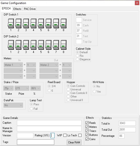
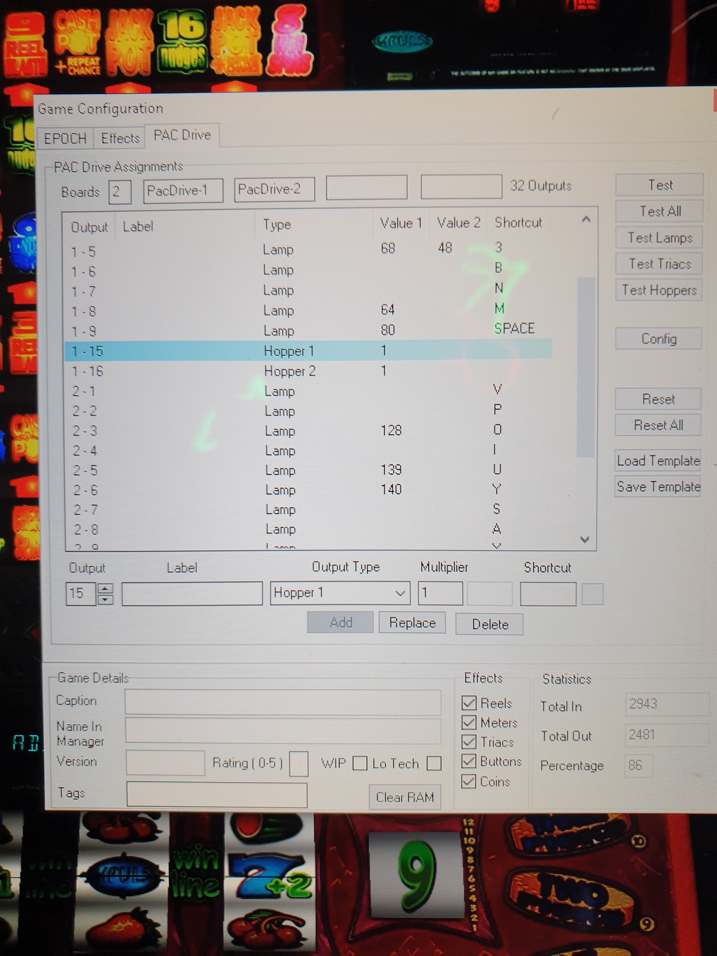
This is funny money on epoch tech. Unfortunately not a lot that I think will be different to mine here but this is how my pacdrive screen is set up for hoppers. As for the layout itself I have done nothing with it to make the payouts work. So try this layout and let me know how it goes.

-
So, now look at WinIPAC, and see which input corresponds to those that you've listed above, and change them to a keyboard shortcut of your choice. maybe 0,9,8,7,6 ? but its upto you. (Or you can leave them as they are)
Now in MFME, you need to create a new lamp, and define it as a coin/note button and select which coin type it is (This will take a bit of working out if you're unsure, but the best place to check is to go into the properties of the £1 coin button that was used on the layout and see what type it is, then choose the same type for 10p/5p/20p/50p) Some trial and error may be required here.
I will have a look shortly and take a photo of my MFME settings on my cab.
And finally, yes, £2 coin is simply the 50p input 4 times. So you don't need to define a £2 coin as it will use the 50p one.
-
17 minutes ago, Psycon said:
Thanks No1Stoney. I will give this a try tomorrow. When you say have the window focused, you mean clicked on so it's got a flashing cursor for example?
Yes That's right.
-
 1
1
-
-
12 minutes ago, Psycon said:
Ahh ok will give this a go. I didn't think it did anything when you clicked it so didn't use it. Again I will try this in the morning thanks

its used to assign lamp numbers to the button shortcuts for each layout. But I am unsure if it also assigns hopper information to the hoppers you have set-up too. I always click the config button when I've loaded in my preset on each layout.
-
1
-
-
5 minutes ago, woodsy said:
Would you recommend I made a mfme keyboard before cabinet? That’s what I’m thinking as I don’t want to ruin my laptop as a start point haha
Yes, definitely. Especially if you have some cheap materials that you can use for the project. The buttons and everything else you buy can be transferrable to a new cab later.
By doing this, you can make sure you figure out how the ipac and pacdrive get wired up and test all that first. I made a button box for my friend who was really keen to get a cab like mine but didn't have the space for it.-
1
-
-
15 minutes ago, Psycon said:
Ahh I will try that for the pounds. I'm sure No1stoney will know what the issue is. I also have the cashflow 126 so hopefully I can get it working tomorrow
Firstly, check you have a light (green?) on your mech to indicate its powered.
Then, to test.. Make sure you have a keyboard press entered into all your wired iPac inputs on WinIPAC..
Then open notepad and have the window focussed.. Insert one of each type of coin and see which keyboard entry it types with each coin and make a note which coin to which key
Now, change those values in WinIPAC to a keyboard entry of your choice.
Then in MFME, each layout, make sure you have a button assigned to the coin and keyboard entry you wish to use for each coin type. You will have to create your own buttons for 5p/20p/50p and usually 10p too as most layouts only have a £1 input by default.. This does take some time if you have many layouts to convert. I always hide these buttons off screen. -
I'm really not sure if this will be of any help whatsoever but always worth trying.. When you setup your hopper in MFME, click the config button before closing the window.
-
Thanks @Reg I had no idea at all that he was against adding support for Pacdrives and hoppers in the beginning. Its amazing to hear that because of our cabinets being built it sparked him into reconsidering, and look how far we have come since then. I remember thinking about all the ways I could work with MFME as it stood (I think it was version 9.4 and 10.1 back then) and 'hacking' into the meter values was the first way in which I managed to get a program to recognise how much my hopper should pay out. I also had to use a 3rd party PCB for controlling the hopper and write some code for that to work correctly. Far from ideal by today's standards, but it was so amazing to get something accepting coins and paying out at all, and I was truly amazed. Once I got a proper coin mech wired up and accepting coins correctly I was so buzzed to get started I couldn't wait.
I also never knew that Chris built his own cab. Did he ever share pictures of this? If so, I'd love to see what he came up with.
Its great seeing everyone's creations come to life and that no two cabs are the same.
-
2
-
-
I believe you can also use money controls universal hopper and suzo's cube hopper. (Parallel versions) but wiring will be slightly different.
Dont go buying these until someone confirms this though as I'm not 100%. I'm sure @Reg you are using universal ?
-
 1
1
-
-
You only need a diode if you want 2 coins to go down the same exit. If you only specify a single coin type to an exit then you don't need a diode. Sorry but I am unsure how to wire these with diodes so cannot help with that
-
The green wire as @Reg has pointed out, shouldn't be there. Pin 7 isn't used for this so should be left empty. Double check your wiring. The mech you have is 21 pin, the diagram I created was for a 17 pin version, however its exactly the same except you connect pins 18/19 to ground as with the other inhibit lines. I believe (although not 100% right now) that the last 2 pins don't need connecting.
-
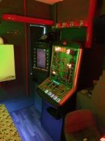
Thats looking spot on @Reg. The cabinet is never truly finished though. Always something else to tinker with. Having said that, my cab hasn't had an upgrade for quite some time.
-
1
-
-
The tiny white plug covering those 2 of the 3 pins on the right. Take it out
Although looking at it, its already in mode 1 as it only sits on 1 pin rather than bridging 2 of them. If that's the case, this won't solve your problem unfortunately
-
1
-
-
Something just occurred to me to try. Just something to rule out... In the hopper there is a jumper pin underneath (I think) take that jumper out if its in there and try again. Your hopper should be on mode 1
Your wiring looks correct
New cabinet build from a beginner
in Cabinet Building
Posted
So what happens now when you try actual payouts? I have 4 of the azkoyen hoppers all rated 24v but all working off the pc's 12v supply. Couldn't tell you what wattage the psu is but I reckon about 350w. I think that 200w would be fine. Also try the test all button