


Amusements
-
Posts
1,897 -
Joined
-
Last visited
-
Days Won
18
Content Type
Profiles
Forums
Gallery
Downloads
Articles
Posts posted by Amusements
-
-
I think you should buy an Arduino kit and play with some code on chat GPT.
Get one of them Arduinos with built in wifi and you should be able to press a button on your phone for a coin out.
-
19 hours ago, Ginge said:
Just wondering is there a reason you picked these hoppers rather than a 12v/24v hopper.
Yes....These are cheap from China, and 12/24v hoppers are not readily available here unless you pay a fortune in postage.
As an example.
Here is a 24v (The only one I can find online here) and it is 82 Squid.
https://shopee.co.th/Coin-Hopper-for-Coin-Exchnage-Machine-i.230857249.22046526098A 220v like the big black one I have, is easy to find, and only cost around 20 Squid, and can hold 1000 tokens.
-
 1
1
-
-
5 hours ago, Ginge said:
220v what hopper are you using not seen one on that voltage.
The black one is 220v and the blue one is 110v
-
1
-
-
5 hours ago, Road Hog Mad said:
Do you have a wire diagram for a button press?
Is it possible for a keyboard press?
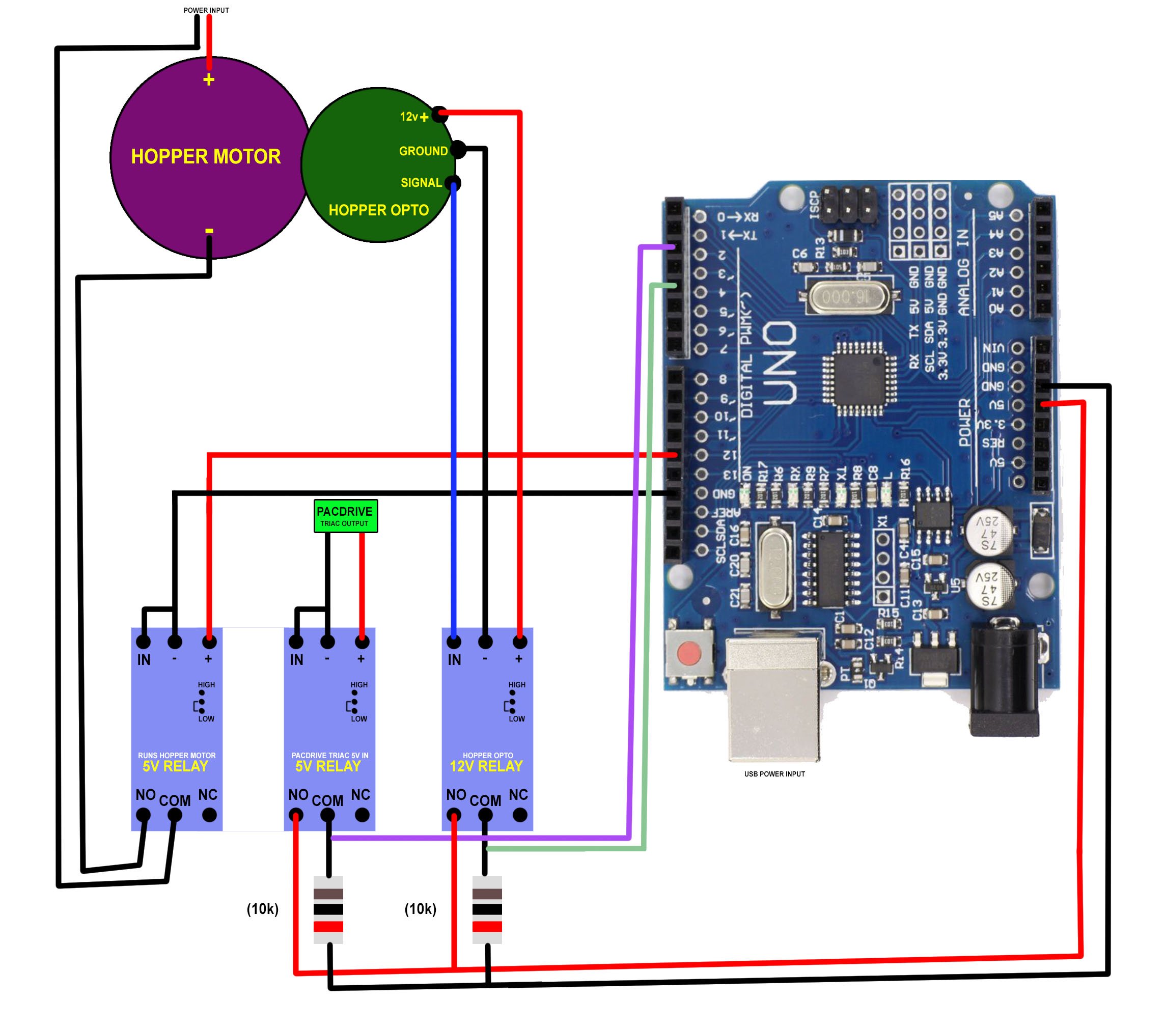
If you change the relay that says PACDRIVE to a switch or button it will spin the hopper until a coin spit out.
//pins
const int pulse = 2;
const int opto = 4;
const int motor = 12;int relaya = 0; // off
int relayb = 0; // offvoid setup() {
// output:
pinMode(motor, OUTPUT);
// input:
pinMode(pulse, INPUT);
pinMode(opto, INPUT);
}void loop() {
relaya = digitalRead(pulse);
if (relaya == HIGH) {
digitalWrite(motor, HIGH);
}relayb = digitalRead(opto);
if (relayb == HIGH) {
digitalWrite(motor, LOW);
}
} -
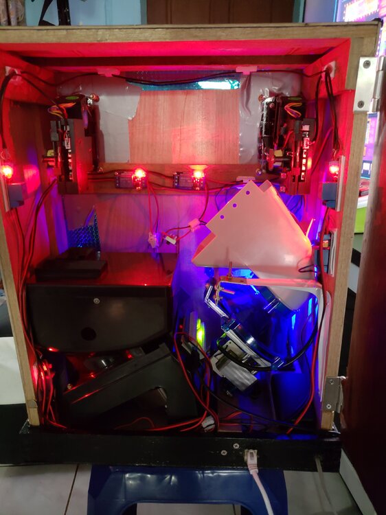
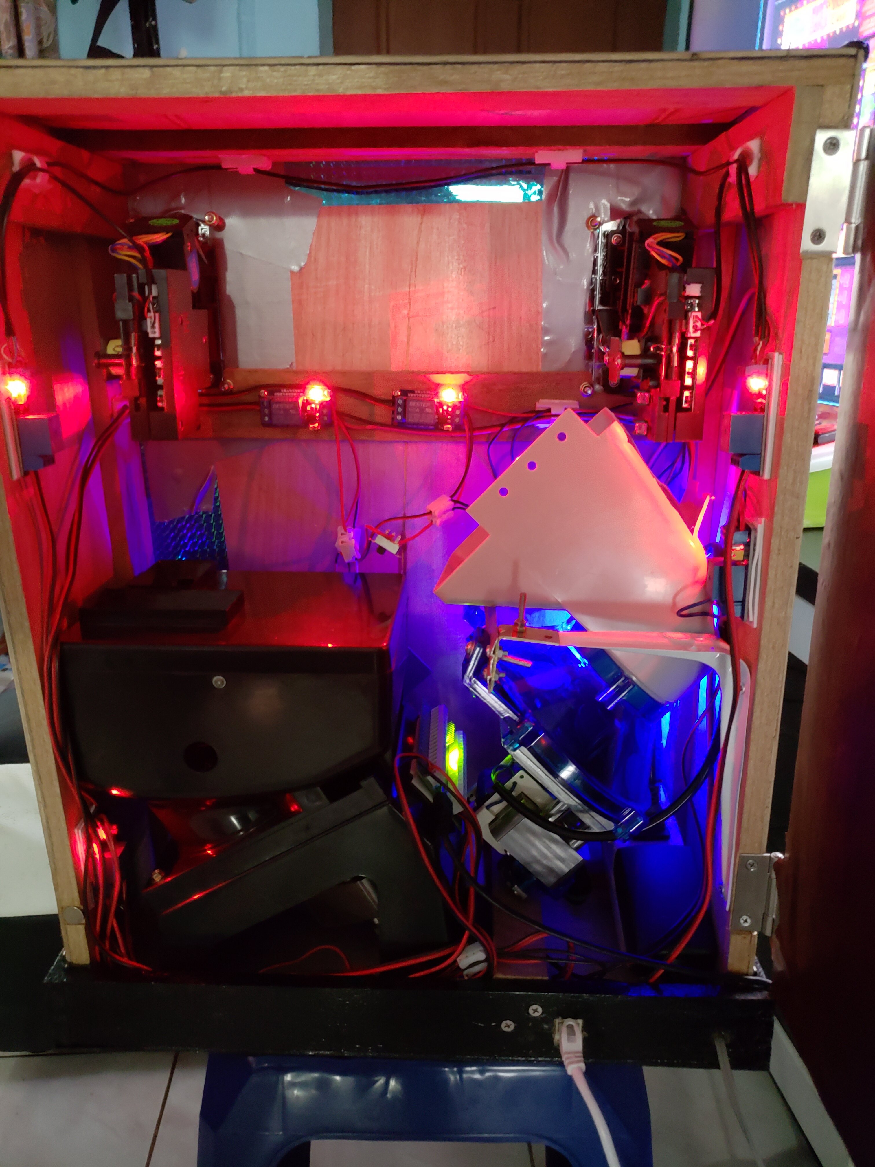
I have done a few things regarding payouts without using a layout.
A key switch that you turn to rotate the hopper (It simply connects the 220v to the hopper motor)
An old kids money box that sets off a couple of timers that spit out x amount of coins, when you insert a note or piece of paper.
A JY-142 board from Aliexpress that converts pulses in - to credits/coins out.
An Arduino Uno that converts a button press to a coin out. (Based on the simple "press a button to light an led" free example)
Another Arduino Uno that converts notes in to key presses using my note acceptor.
I have some old threads in the cab section.
I think it might be possible to make some sort of change machine based on MFME, using some of these new AI tools to program and assemble some code?
-
6 hours ago, Boulderdash said:
Is there a buttons FAQ?
F12 switches between short and long-term meters, for example.
Is there a list of all others? Is there one to reload the layout without saving the ram?
There are these:
-
3
-
-
Ouch!!!
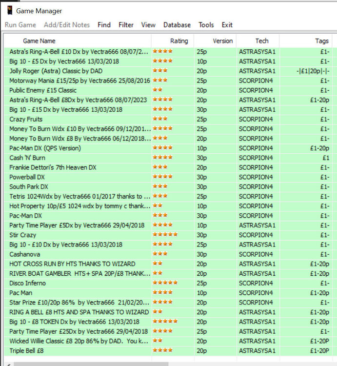
I know how much work it takes to set up layouts on a cab... Mine is set up for over 2000 layouts, and that has taken me a couple of years to do.
The only thing that helped me was to make a Pacdrive template. Once I set the buttons in a layout, I load the Pacdrive template and click Config in Pacdrive settings to fill in the lamp fields. Other than that, it's a lot of time-consuming work.
If he can find someone else with a similar set up and copy their layout folder that would help.
For setting up the coin inputs, this is what I use now to set things up. CREDIT BUTTONS TEST.zip Run this in a separate MFME window and put in to Edit mode, and you can copy and paste the buttons into your layout to test different settings.
-
1
-
-
In simple terms,
The Pacdrive spins up the hopper motor, and the Ipac tells the hopper to stop spinning after a coin passes the optical sensor.
Here is 1 example.
When you get a 1 coin hopper payout, the Pacdrive sends out 5v to a pin out IE: 16. (Or up to 48v with external power.)
This 5v output is what you connect to a relay that completes the circuit to power the hopper motor. (I use 220v hoppers).
The hopper spins round until a coin passes through the optical sensor. This is where the Ipac comes in.
The Ipac is waiting for a connection to be made between ground and a pin on the board you set for the "[" or "]" input. This is done with another relay. I use a 12v one as it is the same voltage as my opto board. When the opto board senses the coin pass, it sends a signal to my relay and that makes the right connection on the Ipac telling the hopper motor to stop spinning.
-
Ultimarc is the main supplier.
Output :: LED and Output Controllers :: PAC Drive (ultimarc.com)
-
 1
1
-
-
7 hours ago, Martinb said:
Regarding the hopper - I was actually wondering being as the operation from the pac drive is so crude (literally ON or OFF) why cant we just wire direct to the motor of the hopper and keep the CC Talk model? I might have a peep at mine to see if that would even work but it can't be that simple, or can it?
In a nutshell, the PacDrive fires 5v to the hopper relay, which gets the hopper spinning. However, it stays on until the opto senses the coin output, and in turn fires a relay, which connects 2 pins on your Ipac, which makes the "[" or "]" key press on your PC.
For triac payouts, you can do away with the Ipac as it does exactly as you say. I use an aduino R3 and route the opto back in to the arduino to stop the hopper spinning.
-
1
-
-
12 hours ago, davep180 said:
Sadly you can’t just swap them around on scorp 4 because the pac drive is looking for a certain keystroke on each hopper. @Amusements had a method which sorted his, but technically, was above my head lol. You will probably be alright, as I’ve seen your work with real machines on the Mecca. Me, not so much. As for line up, it was pre £1 coins so I think you are stuck with 50p max. I just play with tens on those old school ones. If anyone does know a workaround, I would like to hear it. I think I tried having 2 50p inputs, but I don’t think it read both? It’s been a while since I messed with this stuff.
I use a 3-way key switch to cross over the opto connections (coin output sensors), and a separate 3-way switch to cross over the hopper connections from the Pacdrive.
There is a setting in MFME Config to swop the optos over for AstraSYSA1, but not for scorpion 4/5 or impact. IE:
Monopoly Deluxe, Very Rich Geezer, Wild Jackpots (scorpion 4)
Baking Bad (Scorpion 5)
Club Frame & Fortune, Club Big Top, Club Red Hot 6 (impact)The following need the Opto and the hopper switching over:
-
1
-
1
-
-
-
I prefer 16:9 in portrait mode, because you can always add blank space to the top of layouts to make them fit snuggly to the bottom of a cab. 16:9 is also better for the taller layouts with belly glasses and top features.
-
Looks better than the version I had on the C64!
I went to a computer fair at Bell Vue in Manchester back in the 80's. I had a Fiver on me, which was just enough to buy one C64 game. It was a toss-up between Scramble and Qbert. I have forever regretted not choosing Scramble! -
11 hours ago, EdwardFarmer said:
when i put 5p in i have it key binded to F1 on the keyboard
F1 is actually an MFME shortcut for "Borderless", so it may be Better to use a number like 5 or 6.
-
Not really sure what your asking? But....Is this happening on a specific layout or every layout? What coin mech are you using?
-
Alternatively, you could instal Peazip. I use Peazip for both Rar and Zip files.
-
Go to preferences and untick Long Term Meters.
-
There is another one called MGalaxy https://www.mgalaxy.com/. I have not tried it, but it looks like it was built for multiple emus.
-
On 30/09/2023 at 15:40, Road Hog Mad said:
Is there a way in a home build that you make it pay out by the press of a button?
I tried changing a button to hopper 1 but nothing happpened.
Put a key switch in line with the hopper and mains (bypassing the relay powered by the Pacdrive).
-
14 hours ago, Road Hog Mad said:
@Amusements I meant to ask you how you got the note acceptor working, as I always have mates coming round with no change

From what I remember you used a note saving box or something? Care to explain how you did it?
")
For the kids hacked money box way, I use 2 timer relays. One controls the timing for the motor that pulls the note in, and another one times the hopper to pay out 10 coins (in milliseconds). I might have posted more info somewhere?
The other note changer I built, I used a JY-142 timer board and a note accepter.
Quick vid of the timers.
-
1
-
-
You can always add a couple of 2 way switches. One that swops the opto outputs over from one hopper to the other (] to [), and another that swops over the Pacdrive hopper outputs over (15 to 16). I have done this on my cab.
-
There is a "Dual Screen" mode in MFME check box in preferences.
-
-
1
-
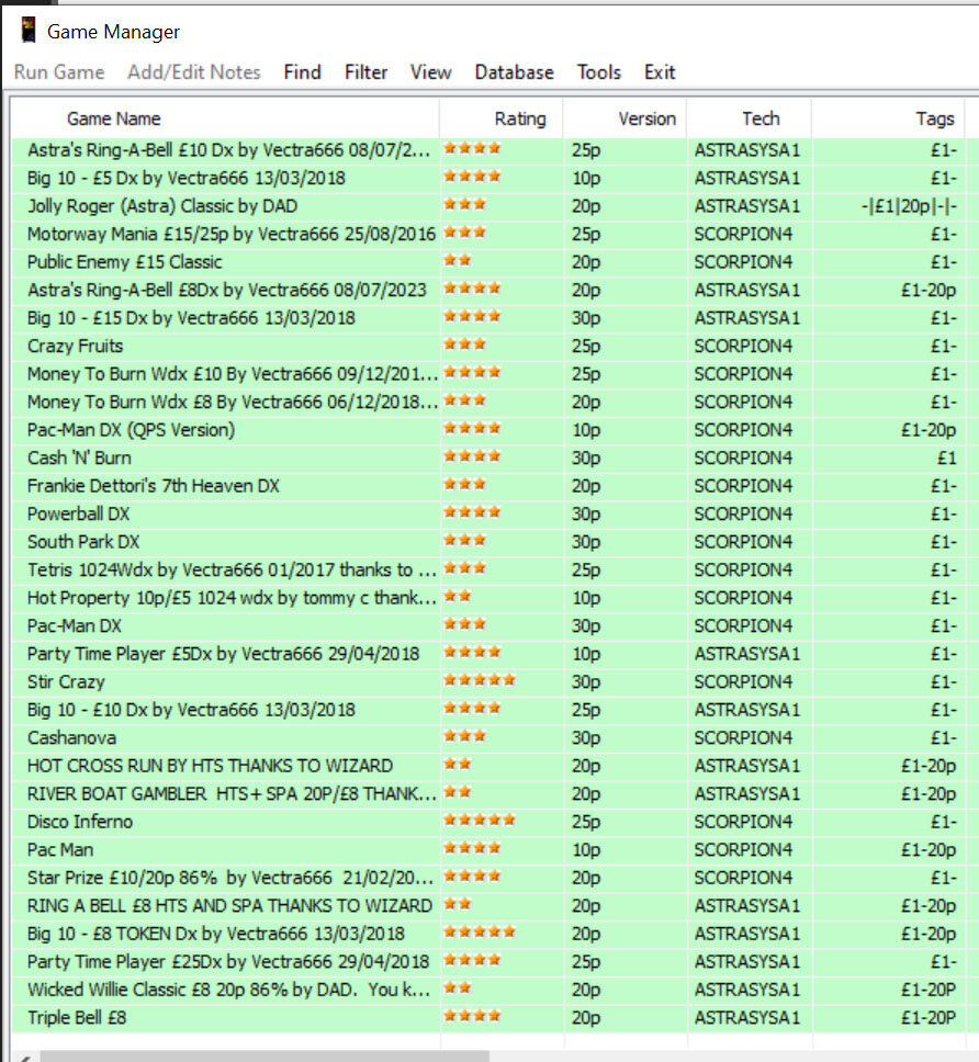
Where do you keep your ROMs/layouts?
in Newbies Help Area
Posted
I always keep a back up of each layout and put in a DX or Classic folder.
I then copy each layout, reset the RAM, top up any hoppers, make sure the sound is on full, and edit the layout for my cabinet in config... I also add a TAG.
You can put in the tag box anything you want, so long as it is one string of characters, and you separate each TAG by a space. Then you can use the filter option in Game Manager.
I then split my layouts in to hopper pay-out configurations.
I then add TAGS to each layout